Jun. 26, 2025
Abstract: This paper introduces the working principle, current status and existing problems of oxygen lance device, and proposes countermeasures for the existing problems.
Keywords: steelmaking converter oxygen lance oxygen lance transmission
The oxygen lance device of steelmaking converter in steelmaking plant includes oxygen lance and oxygen lance lifting device. It is one of the important equipment of pure oxygen top-blown converter. It uses high-quality water-cooled oxygen blowing pipe to send industrial pure oxygen into the blowing of semi-steel or molten iron to complete the task of smelting steel. Its lifting and lateral transmission device cooperates with the relevant equipment of converter tilting machinery through electrical interlocking to complete the operation tasks such as smelting and replacing oxygen lance.
During the blowing process, the oxygen lance needs to be lifted and lowered many times to adjust the gun position. The following requirements are put forward for the lifting mechanism and replacement device of oxygen lance:
(1) It should have a suitable lifting speed and can be variable speed.
(2) The oxygen lance should be lifted and lowered smoothly, with flexible control, safe operation, simple structure and easy maintenance.
(3) The oxygen gun can be replaced quickly.
(4) To ensure safe production, the oxygen gun has a corresponding interlocking device. For example, if the converter is not in a vertical position, the oxygen gun cannot be lowered; if the oxygen gun is lowered into the furnace mouth, the converter cannot be tilted. When the oxygen gun descends to the oxygen opening point, the oxygen valve automatically opens and switches to slow operation; when the oxygen gun is raised to this point, it automatically switches to fast operation; when the oxygen gun is raised to the oxygen closing point, the oxygen valve automatically closes and switches from slow operation to fast operation. When the oxygen supply pressure or the water pressure of the cooling water is lower than the specified value, or the water temperature of the cooling water is higher than the specified value, the oxygen gun automatically rises and alarms.
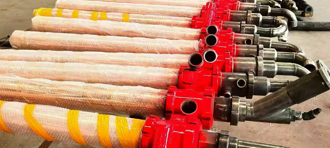
The oxygen lance device consists of an oxygen blowing pipe, an oxygen gun transmission device, a lifting trolley, a lifting trolley slideway and a tube changing device and a transverse trolley, a transverse trolley transmission device, a counterweight, a counterweight slideway, etc.
The oxygen lance is made of 3 concentric seamless steel pipes, with an outer diameter of ф219 and a total gun length of 17355mm. The nozzle currently used is 535. The oxygen blowing pipe is cooled with high-quality water, with a water pressure of 10--12kg/h, a water supply of ≥120t/h, an inlet water temperature of ≤25℃, and a return water temperature of ≥45℃. The oxygen gun cooling water uses a metal hose, model: SA25JRL150A-15500, and the quantity is two. The oxygen delivery hose uses the same metal hose, and the oxygen hose and cooling water pipe are arranged in the east and west respectively.
The lifting and lowering of the oxygen gun is achieved by lifting the counterweight, and the counterweight coefficient is 1.3 times. The two ends of the steel rope are fixed on the pulley support of the lifting trolley and the counterweight. The transmission steel rope has a drum that passes through the pulley of the counterweight and is fixed on the bracket of the small base. When the motor is turned on, the counterweight is lifted or lowered by the Ф800mm drum through the reducer to complete the lifting and lowering of the oxygen gun.
The oxygen lance lifting brake adopts hydraulic brake, equipped with emergency power supply. During the lifting process, when power failure occurs, the brake is opened by another power supply. The oxygen gun is lifted out of the converter body, as shown in Figure 1.
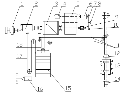
Figure 1
1- convex 50/A self-synchronous machine engine; 2-LK-168/4 master controller; 3-lifting drum; 4-digital display transmitter; 5-reducer; 6-engine;
7-brake; 8-cylinder; 9-stroke indicator instrument; 10-oxygen blowing tube configuration record transmitter; 11-traction steel rope; 12-hanging device; 13-lifting trolley;
14-oxygen lance; 15-balance hammer; 16-scale steel rope; 17-scale steel rope; 18-balance hammer steel rope
The tube replacement device is a trapezoidal hanger, which is suspended by two oxygen gun steel ropes. It has two functions at the same time: one is to hang the car body, and the other is to replace the tube. The new tube replacement mechanism can be used to quickly put the spare gun into blowing. Prevent non-operating time.
The lifting trolley guide rail is four sections in length and connected with screws. A spring buffer device is installed at the bottom of the guide rail to reduce the impact on the platform when the trolley falls accidentally.
The transverse device is transmitted from the motor through the reducer to a lever fixed on the transverse frame at one end. There is a nut on the lever, which is fixed on the transverse frame, and the mechanism moves.
The transverse trolley is welded from steel sections, and two oxygen gun lifting trolleys are installed on it at the same time, one is the working gun used for blowing, and the other is the spare gun. There are four horizontal wheels on the upper part of the frame, and two horizontal wheels and two vertical wheels on the lower part to bear all the weight and eccentric loads.
At present, the oxygen lance devices of the three converters in the steel plant have the following problems
(1) The oxygen lance lifting is now achieved by using a balance hammer. Theoretically, the weight of the balance hammer is 1.3 times that of the oxygen lance, which is greater than the weight of the oxygen lance and can completely lift the oxygen lance. However, the actual use is different from the actual theory. For example, if there is too much slag sticking to the oxygen lance, it is easy to cause the oxygen lance to lift slowly and fail to meet the process requirements.
(2) The oxygen lance balance hammer device makes it difficult to judge equipment failures, because it is necessary to search from the steel rope, pulley, balance hammer body, oxygen lance trolley, etc., which is labor-intensive and time-consuming, and prolongs the equipment failure time. During regular maintenance, the replacement of the oxygen lance trolley, pulley, and steel rope brings great inconvenience, labor-intensive and time-consuming.
(3) It takes time to replace the oxygen lance. The cooling water metal hose is connected by flange. The bolts must be loosened one by one. Due to the long-term high-temperature dust area, the bolts are difficult to loosen. The replacement of the oxygen gun requires manual disassembly by fitters and cranes. The working time is long and the labor intensity is high. In addition, the replacement time of the entire oxygen gun is recorded in the non-production operation time, which affects the availability of the equipment.
(4) The horizontal moving trolley was originally set up for changing the gun. Due to the original design problems, it has not been used for a long time.
(5) There are major safety hazards: if the steel rope is accidentally broken, the heavy weight will fall, damaging the equipment or the oxygen gun will fall into the furnace and burn or a large amount of water will enter the furnace, causing safety accidents.
1) The oxygen lance lifting device of the oxygen gun system should cancel the balance hammer device, cancel the upper pulley, and reconstruct it. The upper drive form is used to directly complete the lifting of the oxygen lance trolley. The oxygen lance lifting system is completed by the motor driving the reel through the reducer. The oxygen gun trolley is lifted and lowered by two steel ropes. Two pulleys are installed on the oxygen lance trolley. The oxygen lance steel ropes go around the pulleys and return to the bottom of the oxygen lance drive device platform. The length of the two steel ropes is adjusted by a balance arm. Steel rope tension sensors are used on the two steel ropes and a value is set to protect and limit the operation of the oxygen lance, as shown in Figure 2.
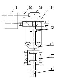
Figure 2
1-reducer; 2-brake; 3-motor; 4-wire rope drum; 5-tension sensor;
6-hanging device; 7-lifting trolley; 8-oxygen gun
This change reduces the number of equipment and simplifies the process. This can save costs and maintenance time.
2) Restore the oxygen lance transverse trolley and restore the configuration of the spare lance. Re-research and design, and the basic form can refer to the vanadium converter oxygen lance transverse trolley: use cycloidal pinwheel reducer, drag chain, adopt easy hydraulic positioning technology, accurately achieve positioning, and achieve the interchangeability of working and spare lances.
3) Design according to elevation. After the oxygen lance transmission device changes, its foundation elevation must have increased. Therefore, the plant structure must also be changed accordingly. On the one hand, the bearing capacity of the current plant should be verified, and research and design should be added. At the same time, the equipment used for maintenance, such as maintenance cranes and maintenance platforms, should also be studied and designed.
4) In the process of replacing the oxygen lance, the metal hose of the oxygen lance adopts a quick joint, and the quick joint of the cooling water pipe should be considered to shorten the lance replacement time and reduce non-production operation time.
Latest News
Latest Products
Customized metallurgical machinery and equipment range: Electric Arc Furnace, Submerged Arc Furnace, LF Refining Furnace, Vacuum Furnace, Induction Furnace, Dust Remove System, Water Treatment Equipment, etc. Providing the most advanced equipment integration services, metallurgical equipment can be customized according to different needs of customers, and production capacity can be adjusted according to customer requirements.
Electric Arc Furnace
Submerged Arc Furnace
LF Refining Furnace
VD / VOD Vacuum Refining Furnace
Induction Furnace
Furnace Accessories
Navigation
E-mail: anna@srfurnace.com
Tel: +86 159 2955 5868
WhatsApp: +86 159 2955 5868
Add:
Room 102, Building 7A, Free Trade Xintiandi, Fengdong Avenue, Fengdong New Town, Xi'an City, Shaanxi Province
